INTRODUCING THE
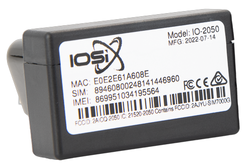
IO-2050 OBD-II Tracker
IOSiX OBD-II
Tracker
Tracker
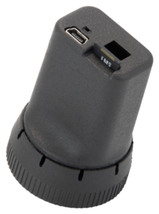
The OBD-II Tracker is our smallest unit yet, without sacrificing reliability or technical expertise.
The IOSiX OBD-II Tracker is our smallest unit yet, without sacrificing reliability or technical expertise. Sacrifice nothing with our plug and play OBD-II Tracker.
This plug and play device records and transmits vehicle data seamlessly over cellular, WiFI, and Bluetooth.
Record and transmit vehicle data seamlessly over cellular, WiFI, and Bluetooth.